- Home
- About CAST
- Core Buisness
- Product & Service
- Contact Us --> --> --> -->
- CAST Profile
-
CAST Subsidiaries
- Qian Xuesen Laboratory of Space Technology (Qian Lab)
- Institute of Spacecraft System Engineering (ISSE)
- Beijing Institute of Spacecraft Environment Engineering (BISEE)
- Institute of Telecommunication and Navigation Satellites (ITNS)
- Institute of Remote Sensing Satellite (IRSS)
- Institute of Spacecraft Application System Engineering (ISASE)
- China Aerospace Components Engineering Center (CACEC)
- CAST-Xi'an Institute of Space Radio Technology (CAST Xi’an)
- Beijing Institute of Control Engineering (BICE)
- Beijing Institute of Space Mechanics and Electricity (BISME)
- Lanzhou Institute of Physics (LIP)
- Beijing Institute of Space Science and Technology Information (BISSTI)
- Shandong Aerospace Electro-technology Institute (SISET)
- Beijing Orient Institute of Measurement and Test (BOIMT)
- Tianjin Institute of Aerospace Mechanical and Electrical Equipment (TIAMEE)
- Beijing Spacecraft Manufacturing Co., Ltd (BSC)
- Shenzhou Investment Management Co., Ltd. (SZIC)
- China Spacesat Co., Ltd. (China Spacesat)
- DFH Satellite Co., Ltd. (DFHSat)
- Space Star Technology Co., Ltd. (SSTC)
- Shenzhen Aerospace Dongfanghong Satellite Ltd. (Shenzhen DFH)
- Space Biotechnology Group (SBG)
- Beijing Ctrowell Technology Corporation Limited (BCTCL)
Beijing Institute of Space Mechanics and Electricity (BISME)
Beijing Institute of Space Mechanics and Electricity (BISME)
l Overview
Beijing Institute of Space Mechanics & Electricity (BISME) was founded in 1958, which is affiliated to China Aerospace Space Science and Technology Corporation (CASC). It’s a professional research institution and main manufacturer in space optical remote sensing payloads in China. As of 2022, it has provided 291 space optical remote sensing cameras for 150 satellites. BISME has the development and application capabilities of the whole process, including design, simulation, production, testing, experimentation, assessment and on-orbit support service. The institute is capable of delivering more than 20 remote sensing payloads each year. BISME is committed to building a high-tech corporation with strong market competitiveness in technological innovation, industrial development, and internationally renowned aerospace core components and applications, and sincerely cooperate with our partners to create a better future.
l Space optical remote sensing camera
With the development of the global commercial aerospace industry, the space optical remote sensing satellite is developing towards the characteristics of high level of integration, miniaturization and constellation (multi-satellites network). The technological process of relevant satellite products has presented the general demand of large quantity and high performance for remote sensing satellite cameras, and accompanied by more diversified customization requirements of users. Based on this, in the field of small satellite and micro-nano cameras, BISME has developed products covering different spatial resolution levels. Their weights range from several kilograms to several hundred kilograms to meet customer demand at different levels.
Ø Beijing-3 satellite camera
Table 1 Key technical indexes of the Beijing-3 satellite camera
|
Items |
Indexes |
|
Band |
PAN: 0.45-0.70μm |
|
Spatial resolution |
0.5m(PAN)/2m(MS) @500km |
|
Width |
12km |
|
Weight |
90kg |

Figure 1 Model of the Beijing-3 satellite camera
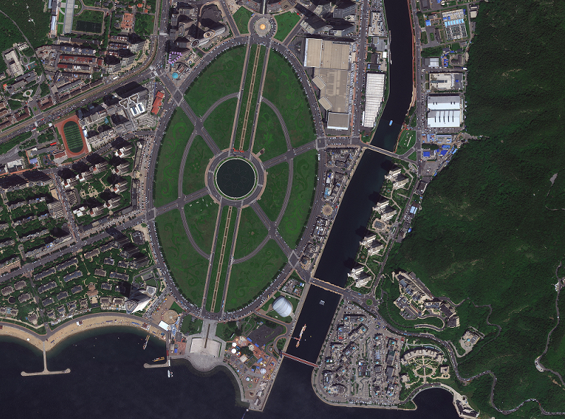
Location: Dalian, China
Figure 2 Image of the Beijing-3 satellite camera
Ø Intelligent remote sensing 01 satellite camera
Table 2 Key technical indexes of the intelligent remote sensing satellite camera
|
Items |
Indexes |
|
Band |
Bayer RGB: 0.42-0.70μm |
|
Spatial resolution |
0.7m @500km |
|
Width |
10km×4km |
|
Weight |
50kg |
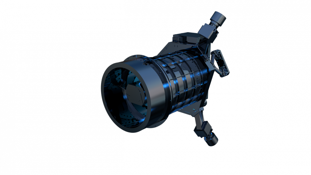
Figure 3 Picture of the intelligent remote sensing 01 satellite camera
Ø Hainan-1 02 satellite high-resolution camera
Table 3 Key technical indexes of the Hainan-1 02 satellite high-resolution camera
|
Items |
Indexes |
|
Band |
RGB |
|
Spatial resolution |
1.5m @500km |
|
Width |
Push broom: 11km; Video: 5.8km×3.2km |
|
Weight |
11kg |

Figure 4 Picture of the Hainan No. 2 high-resolution camera
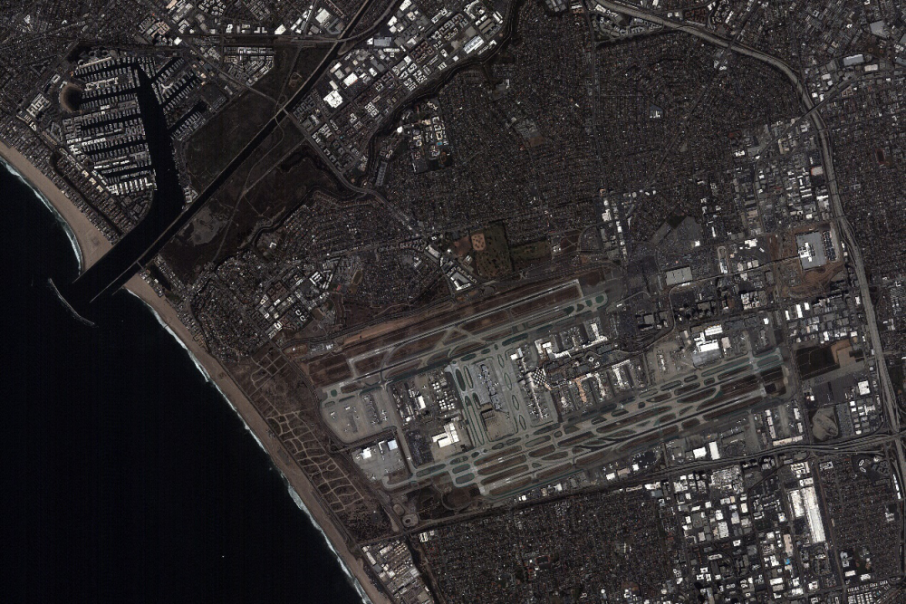
Location: Los Angeles, USA
Figure 5 Image of the Hainan No. 2 high-resolution camera
Ø Taijing-2 01 satellite camera
Table 4 Key technical indexes of the Taijing-2 01 satellite camera
|
Items |
Indexes |
|
Band |
PAN: 0.45-0.90μm |
|
Spatial resolution |
2m(PAN)/8m(MS)@500km |
|
Width |
15.8km×12km |
|
Weight |
3.5kg |
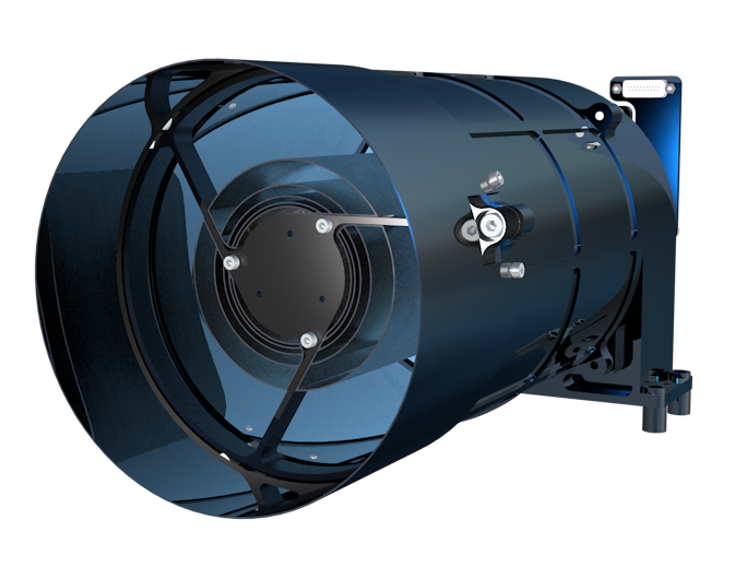
Figure 6 Picture of the Taijing-2 01 satellite camera

Location: Algeciras, Spain
Figure 7 Image of the Taijing-2 01 satellite camera
Ø Hainan-1 01 satellite large-width camera
Table 5 Key technical indexes of the Hainan-1 01 satellite large-width camera
|
Items |
Indexes |
|
Band |
0.77-0.89μm |
|
Spatial resolution |
5m @500km |
|
Width |
115km |
|
Weight |
9kg |

Figure 8 Picture of the HRC4400 camera

Location: Los Angeles, USA
Figure 9 Image of the Hainan-1 01 satellite large-width camera
Ø GF-4 satellite camera
Table 6 Key technical indexes of the GF-4 satellite camera
|
Items |
Indexes |
|
Band |
PAN: 0.45-0.90μm |
|
Spatial resolution |
50m(VNIR)/400m(MWIR) @36000km |
|
Width |
400km×400km |
|
Weight |
410kg |

Figure 10 Picture of the GF-4 satellite camera
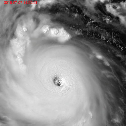
Location: East China Sea
Figure 11 Dynamic image of the typhoon by GF-4 satellite camera
Ø The solar-induced chlorophyll fluorescence imaging spectrometer
Table 7 Key technical indexes of the solar-induced chlorophyll fluorescence imaging spectrometer
|
Items |
Indexes |
|
Band |
0.67-0.78μm |
|
Spatial resolution |
1.5km @500km |
|
Width |
34km |
|
Spectral resolution |
0.3nm |
|
Weight |
107kg |
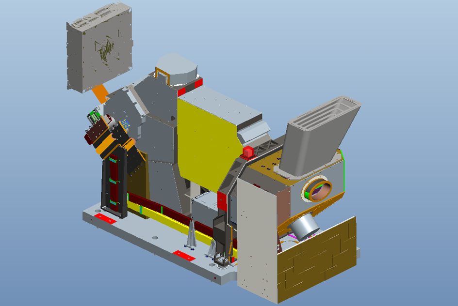
Figure 12 Model of the solar-induced chlorophyll fluorescence imaging spectrometer
Ø The light-small hyperspectral imager
Table 8 Key technical indexes of the light-small hyperspectral imager
|
Items |
Indexes |
|
Band |
0.4-1.0μm |
|
Spatial resolution |
5nm |
|
Field of view |
30°(optional) |
|
Weight |
3kg |
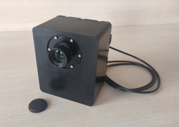
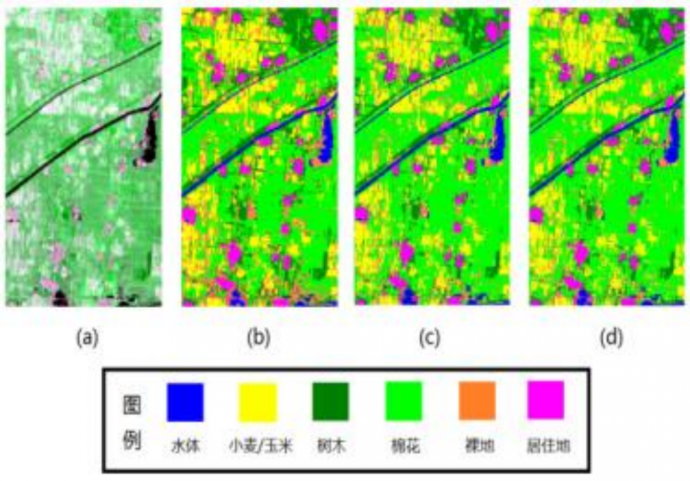
Figure 13 Picture of the light-small hyperspectral imager

Figure 14 Fine classification of crops (Citrus for example)
Ø Mars exploration rover WIFI camera
The WIFI camera of Mars exploration rover developed by BISME captured the group photo of the lander and the rover of Mars, marking the complete success of China’s first Mars exploration mission.
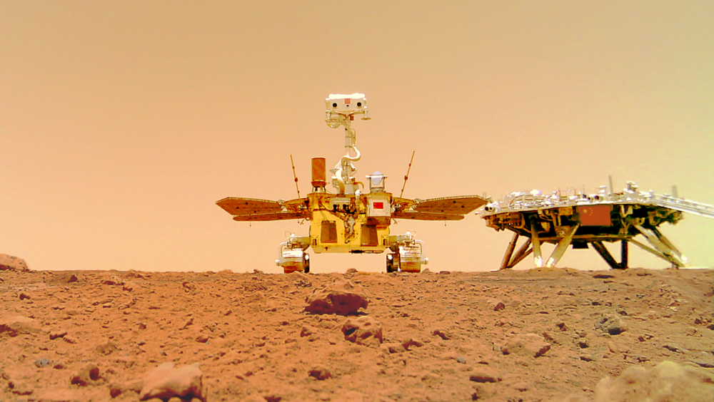
Figure 15 Group photo of the lander and the rover
l Remote sensing data analysis service
Taking advantage of satellites obtain information at large scale, remote sensing data analysis service covering the on-orbit tuning, intelligent evaluation, data processing and quality enhancement based on the payload, as well as image information extraction and application, etc., provides technical solutions, standard and customization system services for domestic and foreign users.
Ø Remote sensing payload tuning
According to the matching relationship between payload parameters and imaging conditions, key performance indexes such as focal plane and imaging parameters are adjusted to ensure that the payload has an optimal state in orbit, so as to obtain high quality image.

Image before focusing
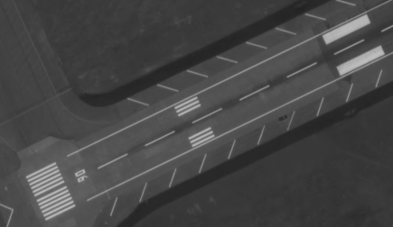
Image after focusing
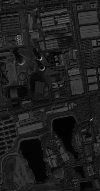
Original image Result after imaging parameters adjustment
Figure 16 Comparison before and after tuning
Ø On-orbit intelligent evaluation of remote sensing payload
According to periodic monitoring results of image and key indexes of the payload, the on-orbit performance and operation state of payload are analyzed independently, so as to ensure the optimal imaging performance of that.
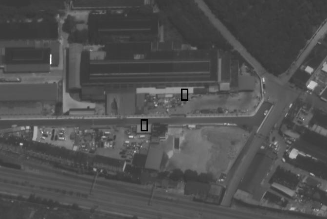
Figure 17 Edge testing
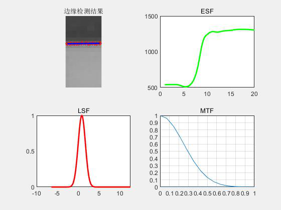
Figure 18 Test result of MTF
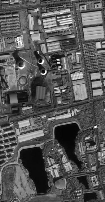
Ø Data processing and quality enhancement based on payload
The method, based on imaging mechanism and payload characteristics, can solve the problem of disconnection between data processing and payload development effectively. On this basis, image quality enhancement services, including adaptive restoration of image super resolution reconstruction combined with imaging system and artificial intelligence, and noise suppression of imaging parameters matching with frequency in image. Compared with the original image, the MTF and resolution are increased by 100%, 50% respectively.
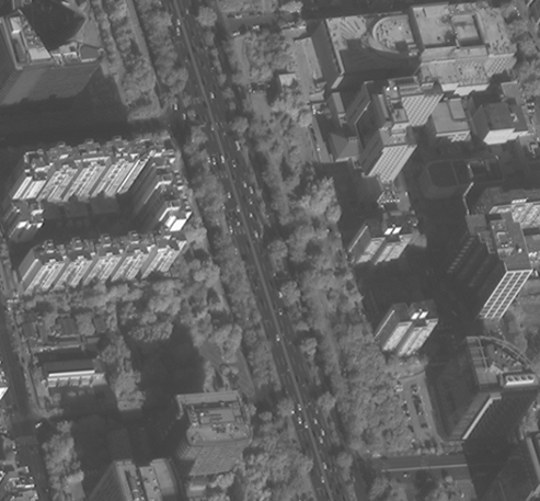
Image before restoration
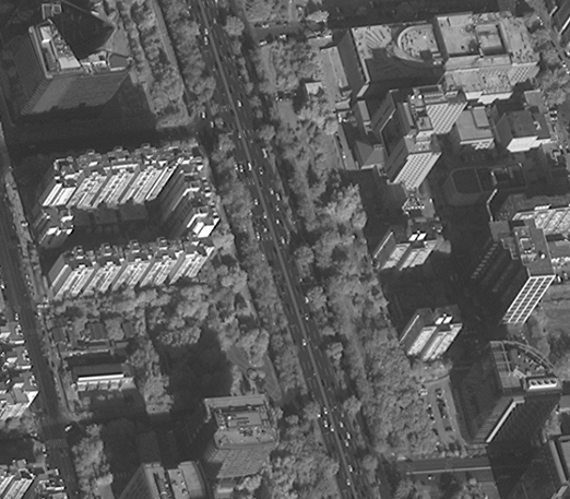
Image after restoration

Image before super resolution reconstruction
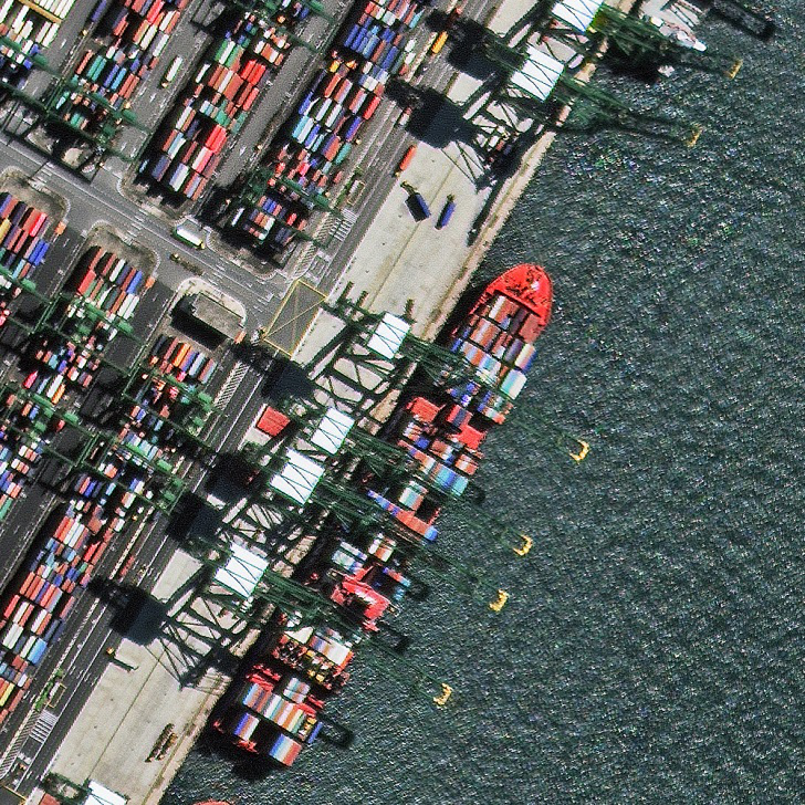
Image after super resolution reconstruction
Figure 19 Comparison before and after data processing and quality enhancement
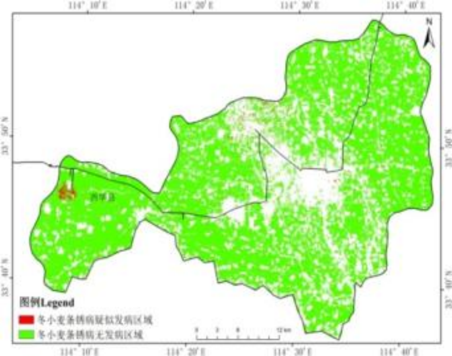
Ø Remote sensing image information extraction and application
Spatial and temporal information is extracted from remote sensing images and applied to the fields of atmospheric environment, resources, agriculture, terrain mapping, etc.
|
Crop disease and pest monitoring |
Agricultural fine classification |
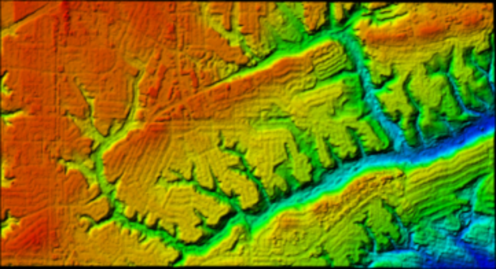
DSM |
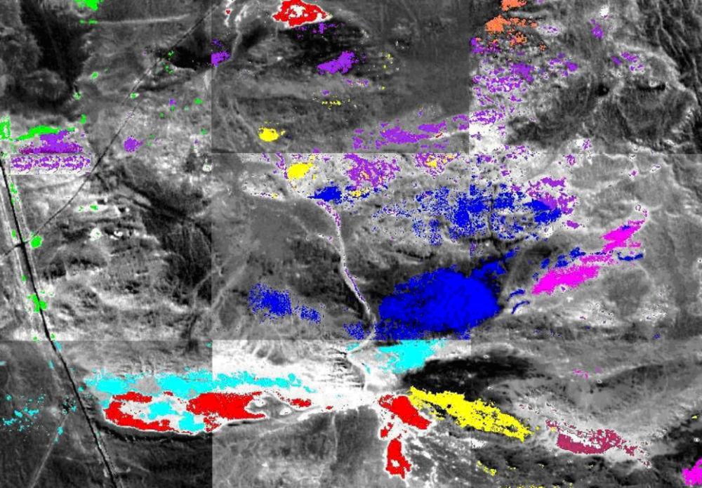
Mineral identification |
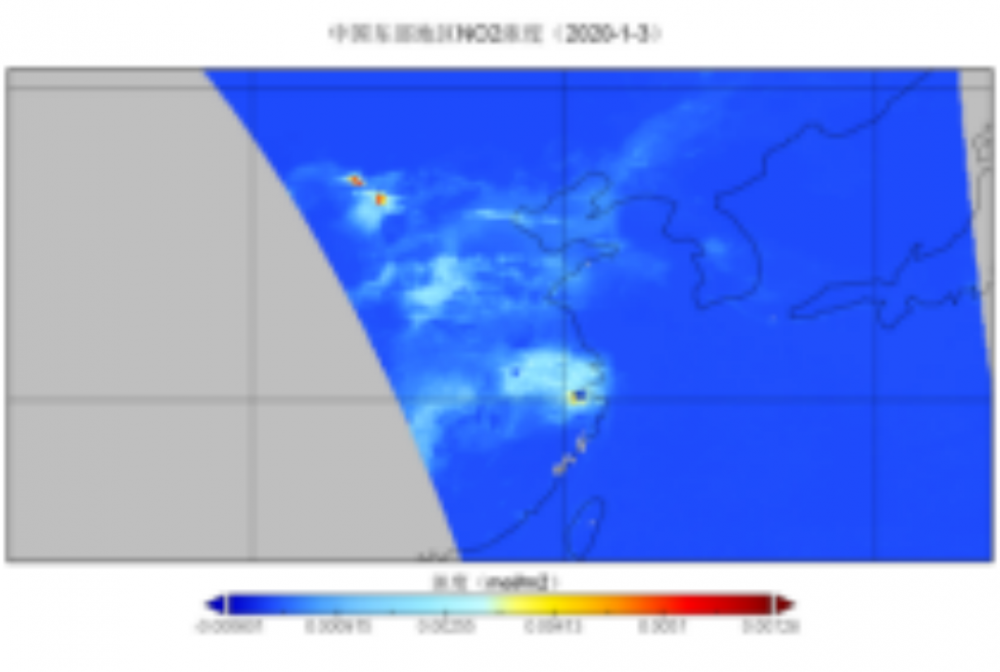
NO2 concentration monitoring |

Water environment monitoring |
l Digital Aerial Photogrammetry System
The AFC-900 ultra-large format aerial survey camera system has a total of over 900 million pixels, making it the world's largest area array aerial survey camera system. The system includes two parts: camera and its control equipment. It also offers optional high-precision POS and airborne stable platform. Integrated with automatic task management and data processing software, it takes the advantages of large format, high precision and high work efficiency, which meets the 1:500 large-scale mapping accuracy requirements, and can provide a reliable and efficient solution for producing high-quality image data.
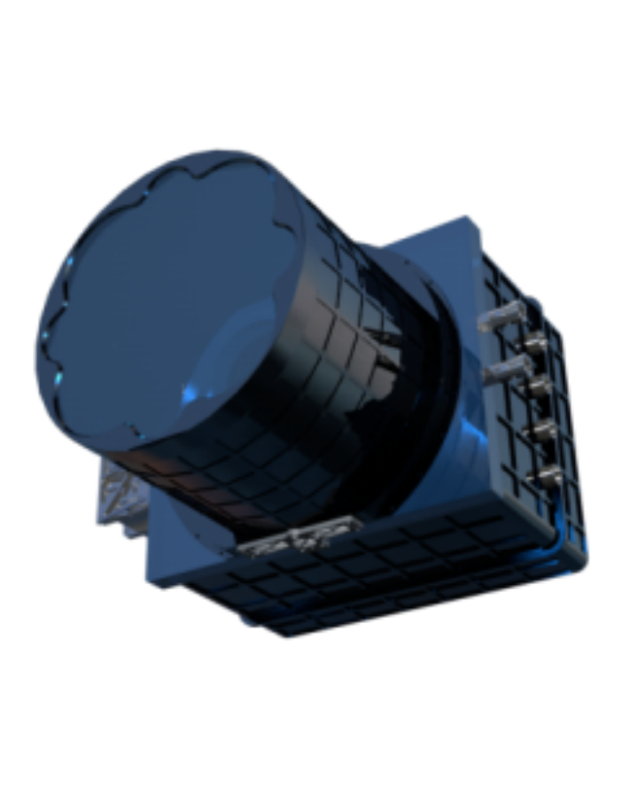
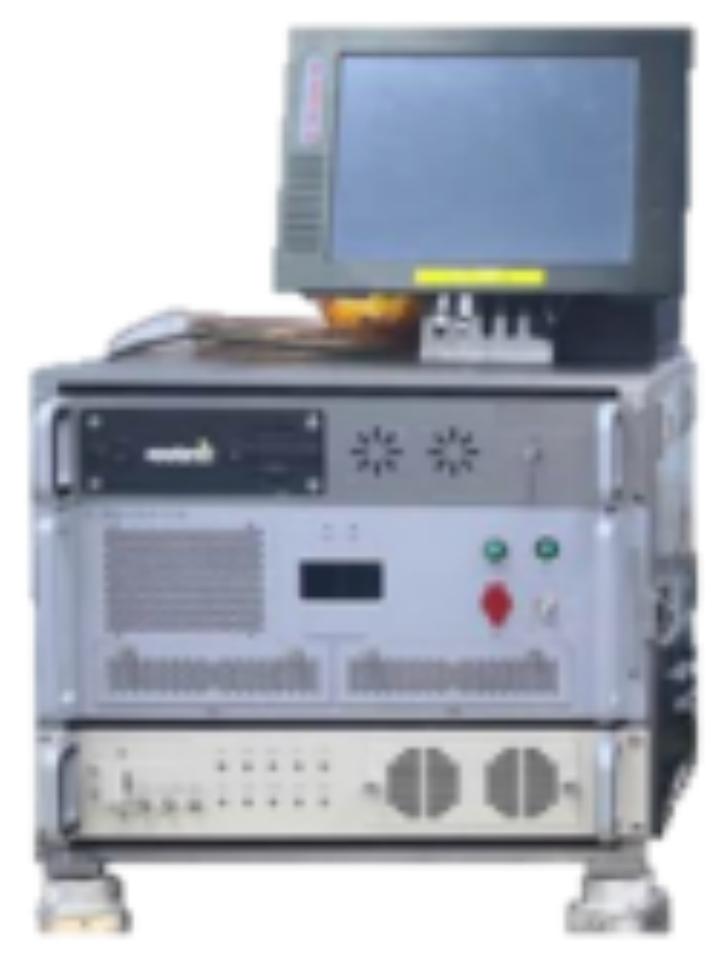
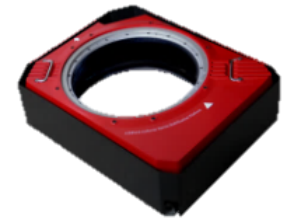
Camera subject Control equipment Stable platform

ask management software Image processing software
Figure 8 Composition of the AFC-900 aerial survey camera system
Ø Comparison of main indicators
Table 4 Comparison of main indicators
|
Parameter comparison |
||||
|
Camera model |
AFC-900 |
DMC III |
Ultra Cam Engle Mark3 |
Ultra Cam Falcon |
|
Manufacturer |
BISME |
Leica |
Microsoft Vexcel |
Microsoft Vexcel |
|
Band |
P/R/G/B/Nir |
P/R/G/B/Nir |
P/R/G/B/Nir |
P/R/G/B/Nir |
|
Sensor size |
30480×28820 |
25728×14592 |
26460×17004 |
17310×11310 |
|
PAN ground resolution@2000m |
0.064m |
0.084m |
0.10/0.080/0.067/0.038m |
0.171/0.120m |
|
Ground coverage@0.1m |
8.78km2 |
3.75km2 |
4.50km2 |
1.96km2 |
|
Field of view |
68° |
64.2° |
76.4°/64.34°/55.33°/33.35° |
83.09°/63.62° |
|
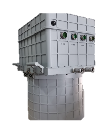
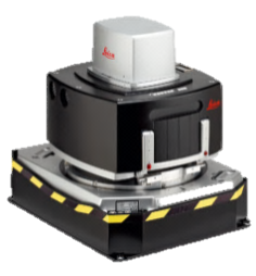
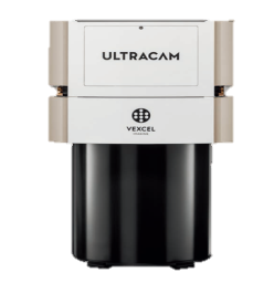
Product picture |
|
|
|
|

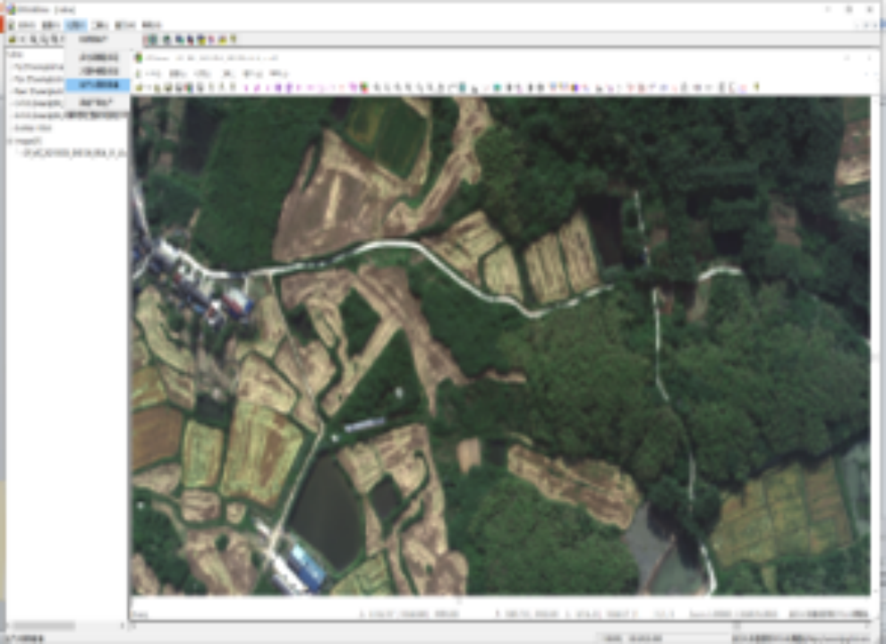
Ø Application cases
The camera system is equipped with near-infrared spectrum which is sensitive to vegetation and water reflectance, and can be used to identify and classify rural villages, agricultural facilities, farmland water conservancy, farmland types etc. It can also evaluate the distribution and growth of vegetate. Besides, the system has good geometric and radiation analysis capabilities for surface coverage and independent features, and can be applied to multiple land exploration application such as surface coverage type recognition and geophysical prospecting target extraction etc.


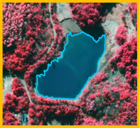
Figure 22 Extraction of agricultural facilities
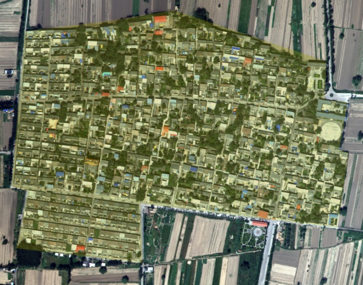
Figure 23 Extraction of rural building land
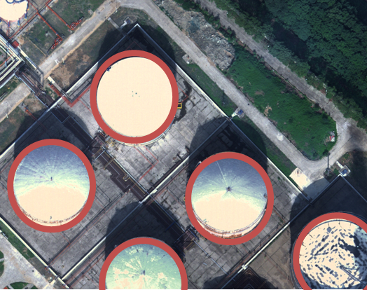
Figure 24 Extraction of petrochemical land and facilities
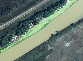
Figure 25 Extraction of tidal flat land
l Composite material structures
BISME has the professional abilities and core technologies of structural design, process design, manufacturing, machining, assembly and testing in the field of resin-based composites, and especially has rich experience in development of high rigidity and high stability remote sensing camera composite structure, lightweight and high strength satellite composite structure.
Ø Frame-strengthened high rigidity main supporting panel

Figure 26 Main supporting panel
· The main supporting panel is a bonded integration, consists of carbon panel, aluminum honeycomb, carbon fiber monolithic frame or assembled frame, and embedded parts.
· Maximum size: 3400mm×4300mm×310mm; Weight: ≤600kg.
· Mounting position tolerance: ≤Φ0.2mm; Mounting coplanarity tolerance: ≤0.05mm.
· Local flatness: ≤0.1mm/100mm×100mm; Total flatness: ≤2mm.
· Mainly used in ultra large, high rigidity and high stability main supporting structures.
Ø High rigidity grid-lattice cylinder
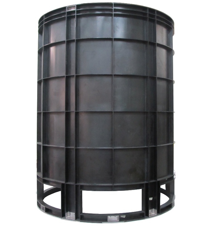
Figure 27 Grid-lattice cylinder
·The Grid-lattice Cylinder is integrated molding by high modulus carbon fiber reinforced cyanate ester resin composite, with the characteristics of lightweight, high rigidity, high strength, low hygroscopic absorption, low expansion.
·Maximum size: Ф1400mm×1810mm; Weight: ≤80kg.
·Mounting position tolerance: ≤Φ0.2mm; Mounting coplanarity tolerance: ≤0.04mm.
·Mainly used in secondary mirror supporting structures of large remote sensing cameras.
Ø Ultra-thin and ultra-light baffle
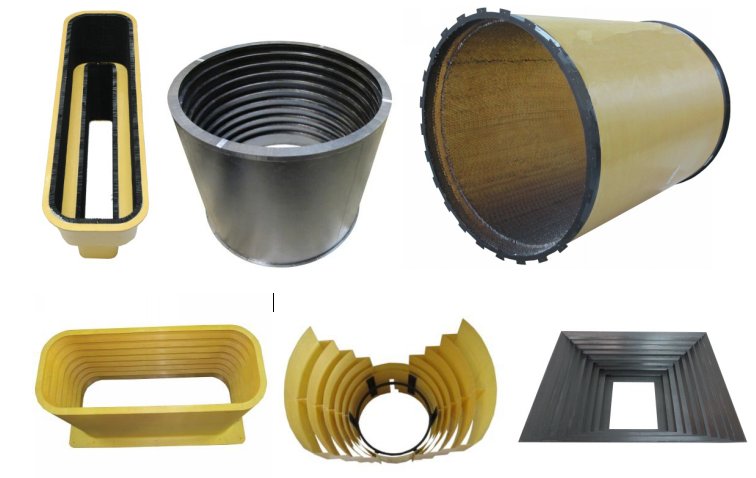
Figure 28 Camera baffle
·The camera baffle is made of fiber (carbon fiber, aramid fiber, glass fiber) reinforced polymer composites or honeycomb (aluminum honeycomb or aramid paper honeycomb) sandwich structures.
·Minimum thickness: 0.3mm; Minimum layer clearance: 1.5mm.
·Mainly used to block and absorb external stray radiation or reduce window temperature gradient to improve the imaging quality.
Ø High-surface-precision reflector of satellite antenna
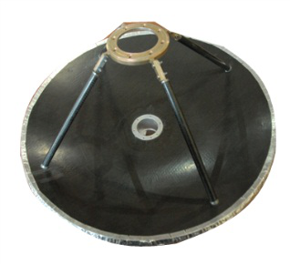

Figure 29 Satellite antenna reflector
·The antenna reflector a bonded integration consists of carbon panel, aluminum honeycomb, and metal embedded parts, with the characteristics of high-surface-precision, high rigidity, lightweight and corrosion resistance.
·Size: Ф600mm; Surface precision (RMS): ≤0.05mm; Weight: ≤1.9 kg.
·Size: Ф700mm; Surface precision (RMS): ≤0.06mm; Weight: ≤2.7 kg.
·Size: Ф1000mm; Surface precision (RMS): ≤0.08mm; Weight: ≤3.2 kg.
·Size: Ф1200mm; Surface precision (RMS): ≤0.10mm; Weight: ≤7.0 kg.
Ø High-temperature-resistant satellite engine bracket
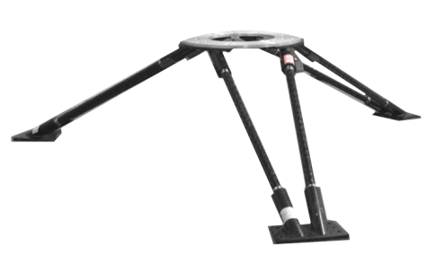
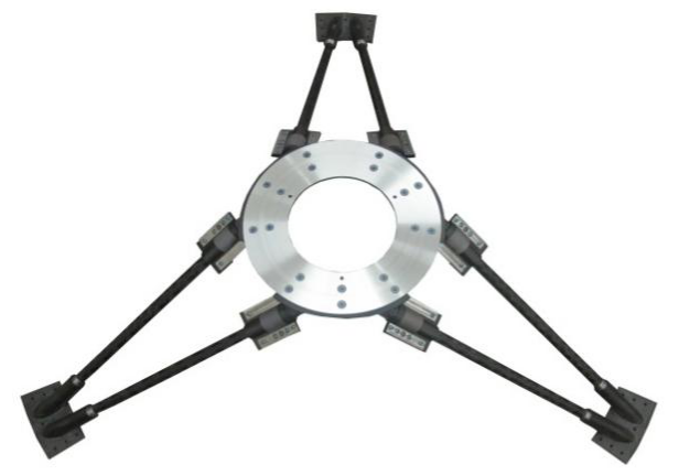
Figure 30 Satellite engine bracket
·The Satellite Engine Bracket is mainly assembled by CFRC joints or metal joints, connecting rods, metal mounting plate. The CFRC joints are formed by 3D braided RTM process and the metal joints by 3D printing technology.
·Size: Ф1140mm×257mm; Weight: ≤2.3kg.
·Size: Ф1535mm×400mm; Weight: ≤3.5kg.
·Parallelism of mounting surface: ≤0.2mm.
·Maximum service temperature: 200℃.
l Thermal products
To promote space remote sensor performance, BISME has types of thermal products which assist lens and structures to reach temperature precision better than ±0.3℃ and high stability. Up to now, more than 60 thermal products have been launched successfully and perform well on orbit. BISME have a wide range of capability in thermal system design, manufacture, assembly and test for types of remote sensors.
Ø Loop heat pipe
Loop heat pipe (LHP) consists of a capillary evaporator (composing of evaporator & accumulator, built-in capillary wick made of non-metallic material), vapor and liquid lines, and a condenser. The working fluid is ammonia.
Applicable scenes: Precise temperature control of core devices (such as photoelectric converting device); Heat transport and dissipation of large-power equipment, such as cryogenic refrigerator, phased-array antenna, etc.
Table 10 Main parameters of LHP
|
Items |
Indexes |
|
Evaporator OD |
φ19~φ25mm |
|
Capillary Pump |
300mm |
|
Vapor/liquid tube diameter |
≤3mm |
|
Working temperature range |
-60℃~+60℃ |
|
Heat transfer capacity |
≥1000W |
|
Heat transfer distance |
≥20m |
|
Precision |
≥±0.5℃ |
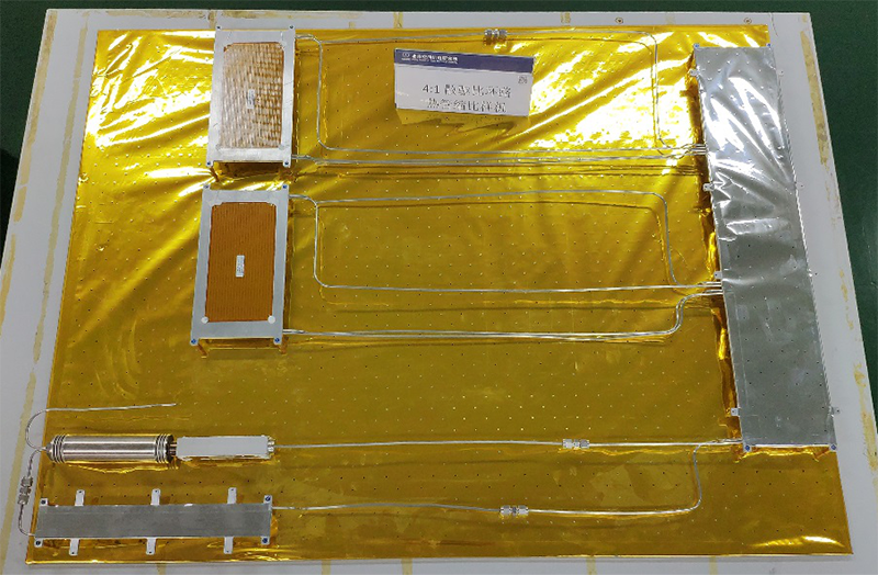
Figure 31 Cylinder loop heat pipe

Figure 32 Flat loop heat pipe
Ø Loop heat pipe
Three-dimensional structure heat pipe integrates the traditional groove heat pipe with the orthogonal micro-channel transfer structure. It can achieve more than 300W heat transfer capability by 1m×1m×1m truss structure. The isothermal ability is better than 2 ℃. This product can greatly improve the temperature uniformity of the spacecraft, Traveling-wave tube (TWT) and Synthetic Aperture Radar (SAR).
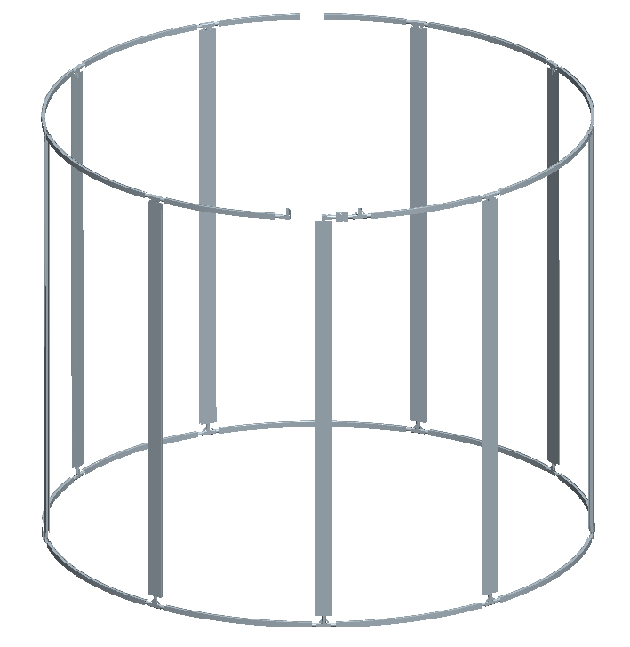
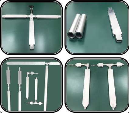
Figure 33 Three-dimensional structural heat pipe
l Optical testing equipment
BISME has profound R&D capabilities in five professional directions: optical design, optical assembly, optical test, radiation calibration, integration and evaluation of assembly system. BISME owns advanced optical test equipment such as large-aperture laser interferometers, precision centering instruments, inner azimuth element testing instruments, stitching instruments, large-aperture long-focal-length collimators, etc. BISME is also equipped with a variety of simulation, design software, which can meet the manufacturing requirements of various advanced remote sensors. BISME has a complete set of mature remote sensor installation and testing production lines, which can meet the installation requirements of cameras with aperture below 1m.

Ø Parallel pipe
The parallel pipe is an ultra-precision optical detection instrument, which is used to generate parallel beam, simulate infinity targets as well as detect and calibrate high-precision optical equipment.
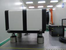
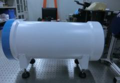
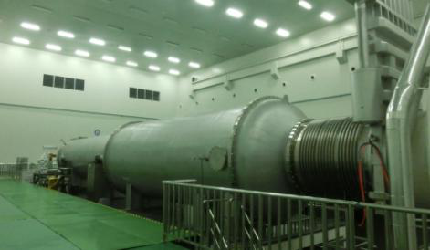
Figure 34 Parallel pipe
·Spectrum: visible~infrared light.
·Focal length: 1m~50m.
·Aperture: 100mm~1600mm.
·Imaging quality: better than λ/15.
·Optical testing under vacuum can be realized.
Ø Stitching instrument
The stitching instrument is suitable for the research and manufacture of focal plane components of visible and near-infrared remote sensing cameras, and different types of focal planes such as linear array type, plane array type and line-plane hybrid type.

Figure 35 Stitching instrument
·Spectrum: visible~infrared light.
·Length of linear array: 1000mm.
·Stitching accuracy: better than 0.4μm.
Ø Inner azimuth element testing instrument
The inner azimuth element testing instrument is used for the main focal point, main focal length and distortion test of the aerospace large-scale-ratio stereo mapping cameras and the aerial measurement cameras.
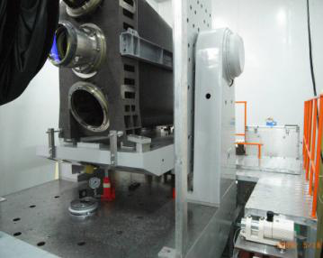
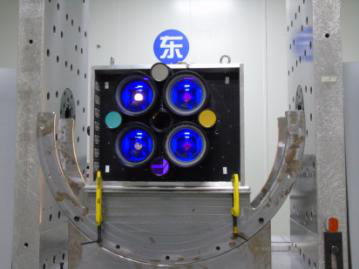
Figure 36 Inner azimuth element testing instrument
·Calibration accuracy of main focal point: <2μm.
·Calibration accuracy of distortion: <3μm.
·Calibration accuracy of inner azimuth element: better than 0.3 pixels.
·Accuracy of self-developed high-precision turntable: better than 1“.